Driving WS2812B LED Strips with an STM32F0, Timers, and Circular DMA
Common individually-addressable RGB LED strips (e.g., NeoPixels, WS2812B, etc.) are controllable via a PWM signal at roughly 800KHz. The duty cycle (i.e., time the signal is spent high in each cycle) of this PWM signal determines if a sent bit is either high or low. In embedded land, specifically on an STM32F0, the typical way to go about this is to use a hardware timer.
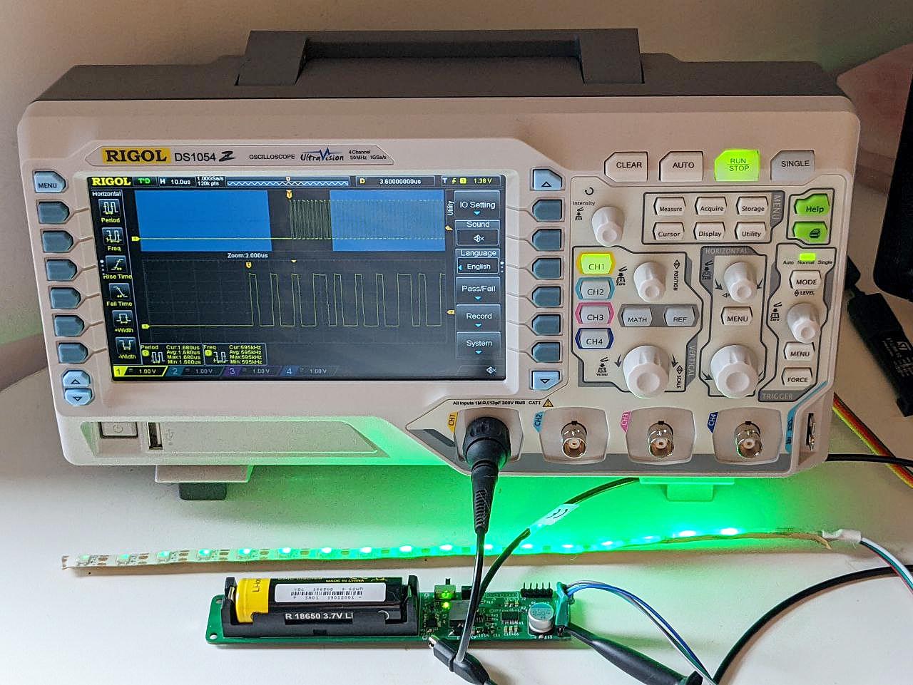
The timer can be configured to generate a PWM signal at the frequency we need with an arbitrary duty cycle, outputting this signal to a GPIO pin which in turn connects to the LED data pin. With that handled, we still need to change the duty at each timer cycle to represent our data bits.
To do this, we could fire an interrupt either as the timer period ends or, even better, as the duty ends in the middle of the cycle. However, the short of it is that the STM32F0 (even at 48MHz) is too slow for this! The timer keeps running during the interrupt and by the time we’ve set the new duty, it’s already squeaked out a couple of extra cycles, rendering the signal invalid.
This is not super accurate but it gives you an idea of what’s going on:
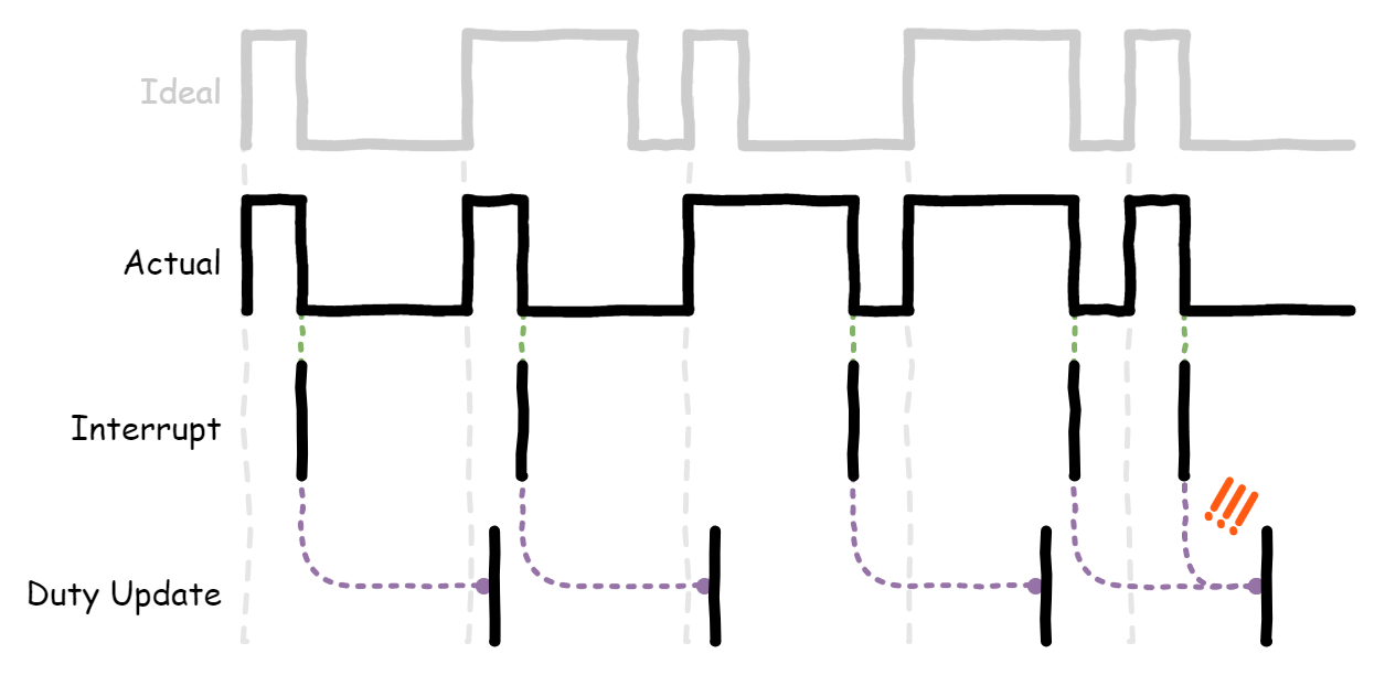
The way around with this is to use DMA, which lets the timer pull duty values from a buffer all on it’s own, just in time for the next cycle. This gives us a new problem though: we’ve got a buffer to maintain.
Each element in our buffer is a byte which represents the duty for that timer cycle. Given that we have a limited amount of memory available — just 4KB — it would be unwise for us try and stuff the entire sequence into the buffer all at once! If we had 100 LEDs, this would require 2.4KB (100 × 24 bits) of memory which leaves little left for anything else.
So, the way round this is to limit the buffer to a smaller size and fill it with more data as we go along. The DMA peripheral can raise an interrupt when it’s both half-way and all the way through the buffer, letting us fill it with more data each time. If we configure the DMA to run in circular mode (i.e., once it reaches the end of the buffer, it wraps round to the beginning of the buffer again), we can continually fill each half with data while it bangs out the other half.
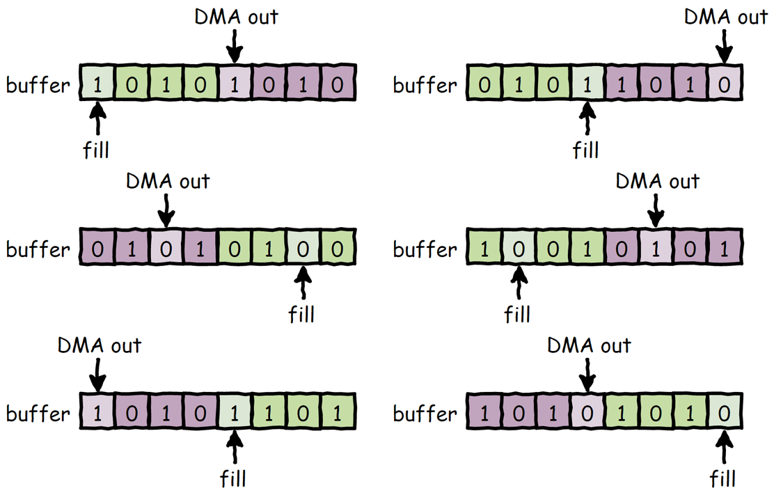
Timers, interrupts, DMA, circular buffers, etc. are all Known Entities™ but I wanted to dive a little deeper on how I went about doing this myself.
Signal Timings and Protocol
For some background, a glance at the WS2812B datasheet tells us exactly what we should send over the data lines. In summary, the signal should look like this:

- The core of it is a PWM signal at 800KHz (±150KHz) or 1.25µs (±600ns) per cycle, where each cycle represents one bit of data.
- Bit level is defined by the duty cycle (i.e., duration spent high).
- Low (0) at 32% duty (0.4µs).
- High (1) at 62% duty (0.8µs).
- Each LED expects 24 bits of colour data: GRB ordering (green, red, blue — instead of the usual RGB), 8 bits per channel, MSB-first. Any number of bits sent after the initial 24 is passed on to the next LED in succession.
- Once all bits are sent, the signal must be held low for at least 50µs to reset and complete transmission.
Getting Started
Before diving in, some quick notes on my setup.

- The MCU is an STM32F030F4, capable of running at 48MHz with 4KB RAM and 16KB flash.
- My development board is custom, specifically for driving these strips.
- I’m using the low-level STM32Cube libraries. HAL didn’t work for me initially, and it was a better way to learn about the registers, etc. without having to do boring bit math.
- I won’t go over system clock setup, etc. tl;dr though: 8MHz HSI * x12 PLL = 48MHz on system and APB/AHB clocks.
- The LED strips are WS2812Bs.
Defines and Buffer Setup
We create some defines to help us later on, and initialize our buffers and related friends:
#define LED_COUNT 100 // Number of LEDs along the strip

#define TIMER_AAR 59
#define DUTY_0 18 // (32% of 59)
#define DUTY_1 38 // (62% of 59)
#define DUTY_RESET 0

// Number of LEDs worth of duties to buffer. Any less than this gave me some
// spooky glitches but YMMV.
#define BUFFER_LED_COUNT 16
#define BUFFER_LED_COUNT_HALF (BUFFER_LED_COUNT / 2)

#define BUFFER_LEN (BUFFER_LED_COUNT * 24) // 24 bits for each LED buffered
#define BUFFER_LEN_HALF (BUFFER_LEN / 2)

#define BUFFER_L_OFFSET 0
#define BUFFER_H_OFFSET BUFFER_LEN_HALF

// Each element represents the GRB value for that LED index e.g., 0x00ffffff is
// full white, 0x00ff0000 is full green, etc.
uint32_t grb[LED_COUNT];

// Offset into the GRB array as we output the LEDs.
uint16_t grb_offset = 0;

// This buffer is used for DMA. Each element represents a duty cycle for that
// timer period index.
uint8_t buffer[BUFFER_LEN];
Peripheral Setup
We need to configure the GPIO pin, the timer, and the DMA channel. For my particular setup:
- TIM1 is, arbitrarily, the timer of choice. It supports PWM output and can trigger DMA requests.
- GPIOA pin 10 (PA10) is used as the output pin, which can be configured as TIM1 output-compare (OC) channel 3.
- TIM1 OC channel 3 uses DMA channel 5.
The following bit of code sets up everything as needed:
void led_init() {
  LL_TIM_InitTypeDef tim_init = {0};
  LL_GPIO_InitTypeDef gpio_init = {0};
  LL_TIM_OC_InitTypeDef tim_oc_init = {0};

  // Enable the clocks for the peripherals we need.
  LL_APB1_GRP2_EnableClock(LL_APB1_GRP2_PERIPH_TIM1);
  LL_AHB1_GRP1_EnableClock(LL_AHB1_GRP1_PERIPH_DMA1);
  LL_AHB1_GRP1_EnableClock(LL_AHB1_GRP1_PERIPH_GPIOA);

  gpio_init.Pin = LL_GPIO_PIN_10;
  gpio_init.Mode = LL_GPIO_MODE_ALTERNATE;
  gpio_init.Speed = LL_GPIO_SPEED_FREQ_HIGH;
  gpio_init.Alternate = LL_GPIO_AF_2; // TIM1 OC channel 3
  LL_GPIO_Init(GPIOA, &gpio_init);

  // An autoreload value of 59 (TIMER_ARR) with a 0 pre-scaler gives us 800KHz
  // or 1.25us at 48MHz.
  tim_init.Autoreload = TIMER_AAR;
  tim_init.Prescaler = 0;
  tim_init.CounterMode = LL_TIM_COUNTERMODE_UP;
  LL_TIM_Init(TIM1, &tim_init);
  LL_TIM_EnableAllOutputs(TIM1);

  // With PWM mode 1, the output is high when the counter is <= the compare value,
  // otherwise it is low.
  tim_oc_init.OCMode = LL_TIM_OCMODE_PWM1;
  tim_oc_init.OCState = LL_TIM_OCSTATE_ENABLE;
  tim_oc_init.CompareValue = DUTY_RESET;
  LL_TIM_OC_Init(TIM1, LL_TIM_CHANNEL_CH3, &tim_oc_init);
  LL_TIM_OC_EnablePreload(TIM1, LL_TIM_CHANNEL_CH3);
  LL_TIM_EnableDMAReq_CC3(TIM1); // Trigger a DMA request on a comparison event.

  // TIM1->CCR3 is the compare register a.k.a. the duty cycle.
  LL_DMA_SetPeriphAddress(DMA1, LL_DMA_CHANNEL_5, (uint32_t)&TIM1->CCR3);
  LL_DMA_SetDataTransferDirection(DMA1, LL_DMA_CHANNEL_5,
    LL_DMA_DIRECTION_MEMORY_TO_PERIPH);

  LL_DMA_SetMode(DMA1, LL_DMA_CHANNEL_5, LL_DMA_MODE_CIRCULAR);
  LL_DMA_SetPeriphIncMode(DMA1, LL_DMA_CHANNEL_5, LL_DMA_PERIPH_NOINCREMENT);
  LL_DMA_SetMemoryIncMode(DMA1, LL_DMA_CHANNEL_5, LL_DMA_MEMORY_INCREMENT);

  LL_DMA_SetChannelPriorityLevel(DMA1, LL_DMA_CHANNEL_5,
    LL_DMA_PRIORITY_VERYHIGH);

  // In this case, TIM1 is a 16-bit counter so it follows that the compare
  // register is also 16-bits wide. Since we only ever count to 59, though, we
  // can get away with storing our duty values as 8-bit values only. The DMA
  // peripheral can handle alignment back to 16-bits on our behalf.
  LL_DMA_SetPeriphSize(DMA1, LL_DMA_CHANNEL_5, LL_DMA_PDATAALIGN_HALFWORD);
  LL_DMA_SetMemorySize(DMA1, LL_DMA_CHANNEL_5, LL_DMA_MDATAALIGN_BYTE);

  LL_DMA_EnableIT_HT(DMA1, LL_DMA_CHANNEL_5); // Triggered half-way through the buffer.
  LL_DMA_EnableIT_TC(DMA1, LL_DMA_CHANNEL_5); // Triggered at the end of the buffer.
  NVIC_EnableIRQ(DMA1_Channel4_5_IRQn);
}
Sending Data
A rough plan of how we’ll manage the transmission process:
- Reset everything and start the timer.
- Fill up the buffer.
- Reset the DMA pointers.
- Enable the timer.
- During transmission, continually update each half of the buffer.
- After the half-way mark, update the lower half.
- After the end mark, update the upper half.
- Repeat until we’ve sent out all the bits, including a full cycle of resets (i.e., 0% duty — more on this later).
- Stop the timer.
Getting everything started is the easy part, so we’ll start from the end. How do we manage the buffer?
Filling The Buffer
Filling the buffer is straight-forward. Some bit shifting and masking gets us the individual bits of the GRB value, which we can then use to insert the correct duty into the buffer.
void led_fill_buffer(uint32_t offset, uint32_t length) {
  for (uint32_t i = offset; i < length; i++) {
    uint32_t grb_i = grb_offset + (i / LED_BPP);

    if (grb_i >= LED_COUNT) {
      // Pad anything outside of the GRB buffer range with resets (0% duty).
      buffer[i] = DUTY_RESET;
    } else {
      // Since the LEDs expect MSB-first, we need to do some fiddling to fire
      // that out first.
      uint32_t grb_value = grb[grb_i];
      uint8_t grb_bit_offset = 23 - (i % 24);
      uint8_t grb_bit = (grb_value >> grb_bit_offset) & 1;

      if (grb_bit == 1) {
        buffer[i] = DUTY_1;
      } else {
        buffer[i] = DUTY_0;
      }
    }
  }
}
Since it’s possible that current RGB offset exceeds the number of LEDs we actually have, we pad the rest with the reset duty. This causes the output to be completely low for the entire duration of the timer cycle. During the transmission process, we always force the RGB offset to go into this state. Again, more on this later.
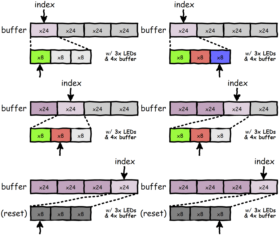
Just to press the point a bit more, the above (very simplified) animation shows the remainder of the buffer being padded with resets after we’ve ran out of GRB data.
Handling DMA Interrupts
Our DMA handler is split into two sections: one for when we’re half-way through the buffer, and one for when we’re at the end of the buffer and about to circle around. Both sections do the same thing, but operate on opposite ends of the buffer. This animation took forever to make so I’m using it again:

You can see how we update one half while the other is read out. Here’s the code that makes that happen:
void DMA1_Channel4_5_IRQHandler() {
  if (LL_DMA_IsActiveFlag_HT5(DMA1)) {
    // We're half-way through.

    // Fill the lower half of the buffer as the top half is now being read.
    led_fill_buffer(BUFFER_L_OFFSET, BUFFER_LEN_HALF);

    LL_DMA_ClearFlag_HT5(DMA1);
  } else if (LL_DMA_IsActiveFlag_TC5(DMA1)) {
    // We're at the end. DMA is about to circle round.

    // Only disable the counter if we've completed at least half a cycle beyond
    // the LED count. This means we'll get a whole buffer's worth of reset,
    // even in the case where the buffer is a perfect fit or more for the
    // number of LEDs.
    if (rgb_offset > LED_COUNT) {
      LL_TIM_DisableCounter(TIM1);
    }

    // Fill the upper half of the buffer as the lower half is now being read.
    led_fill_buffer(BUFFER_H_OFFSET, BUFFER_LEN_HALF);
    rgb_offset += BUFFER_LED_COUNT;

    LL_DMA_ClearFlag_TC5(DMA1);
  }
}
Reset Padding
So, why wait for at least a half cycle of resets before stopping? Simply put: calling the stop timer function (or setting the register directly) takes time. By the time the bit has been set and acknowledged, the timer will have already ran through a couple of cycles. If we didn’t fill next section the buffer with resets, this would mean we would be sending out data for LEDs that don’t exist.
There’s more to it than that, of course. You might now be thinking to yourself: surely that doesn’t matter anyway? The final LED will have already taken it’s 24 bits and will just be throwing away the rest! And that’s true, but it’s nice to be neat and tidy! Don’t wiggle the signal in ways that you don’t need.
Actually though, there’s a genuine problem this solves. When the timer stops, it’s not guaranteed that it’ll be during the low part of the duty cycle. The output is frozen at this point, so if the output was high then it’ll stay high until the timer is started again. This is 100% No Bueno as we need the output to stay low for at least 50µs for our the LEDs to update! Look at this mess:
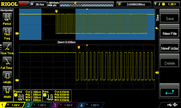
This is why we need to make sure the timer gets hit with some 0% duty before we stop it. That way, the output will be completely low until we start the process all over again.
Kicking Things Off
Finally, now the easy part. To get things going, we can run the following:
void led_update() {
  rgb_offset = 0;

  // Fill up the buffer completely!
  led_fill_buffer(BUFFER_L_OFFSET, BUFFER_LEN);
  rgb_offset = BUFFER_LED_COUNT;

  // Reset the DMA channel to point at the start of the buffer.
  LL_DMA_DisableChannel(DMA1, LL_DMA_CHANNEL_5);
  LL_DMA_SetMemoryAddress(DMA1, LL_DMA_CHANNEL_5, (uint32_t)buffer);
  LL_DMA_SetDataLength(DMA1, LL_DMA_CHANNEL_5, BUFFER_LEN);
  LL_DMA_SetMode(DMA1, LL_DMA_CHANNEL_5, LL_DMA_MODE_CIRCULAR);
  LL_DMA_EnableChannel(DMA1, LL_DMA_CHANNEL_5);

  LL_TIM_EnableCounter(TIM1);
}
Calling this will reset everything and kick off the timer, starting the data transmission process.
Wrapping Up
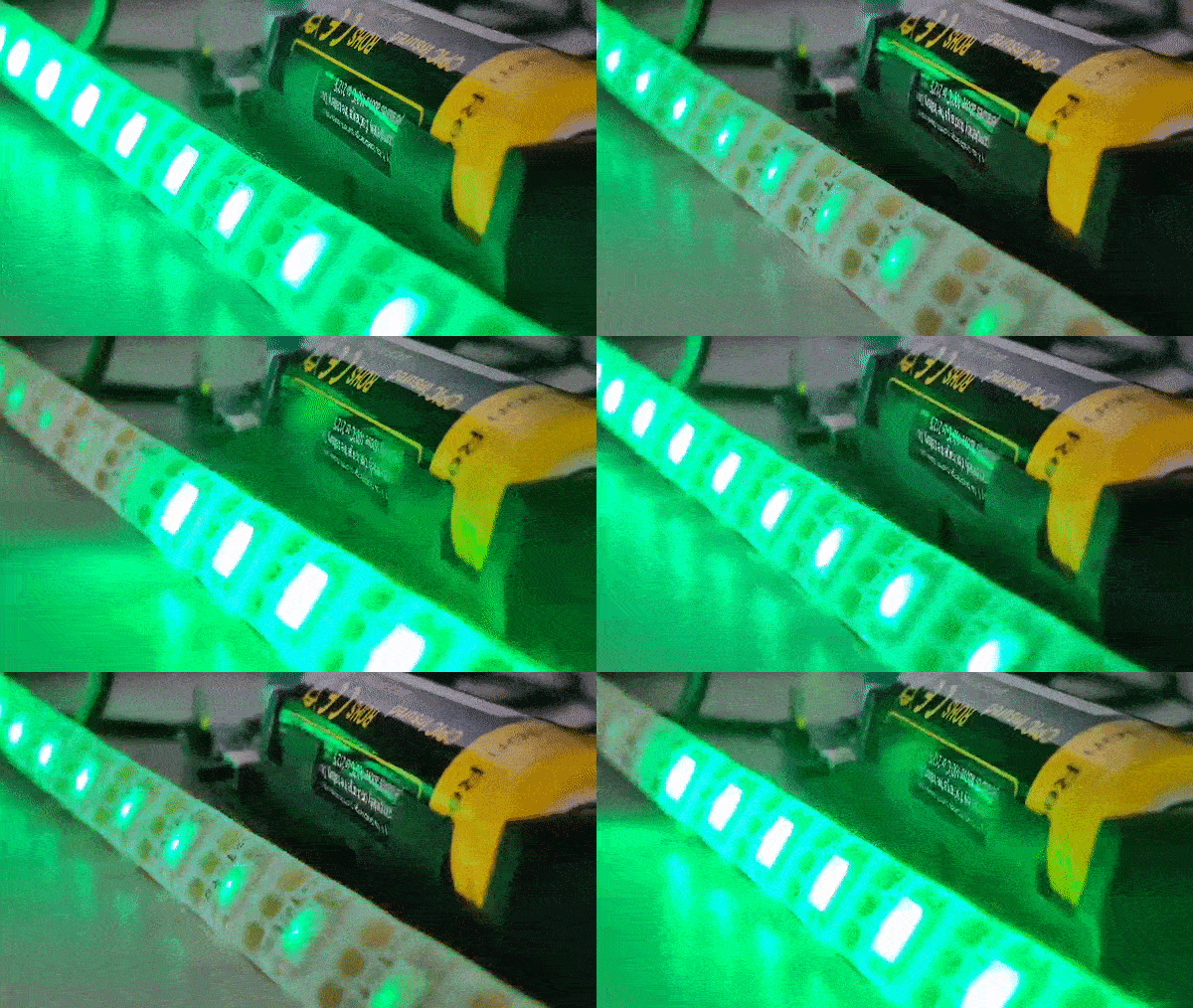
With all that dealt with, we can get on with the cool animations. Once the grb array is modified
with our colours of choice, we can call led_update() to send out the data.
Since GRB is a garbage format and everyone loves RGB instead, here’s a bonus macro you can use to convert individual RGB bytes to GRB words:
#define GRB_WORD(R, G, B) (((G) << 16) | ((R) << 8) | (B))To conclude, this was a very long-winded way of saying:
- Use a timer and DMA to fire bits out a PWM signal over the LED data pin. The duty cycle represents a high or low bit.
- Use a circular DMA buffer, updating half of the buffer with the next set of bits while the other half is sent out.
- Stop the timer when we come to the end of the buffer, just after we’ve filled the lower half of the buffer with zero duty. Since it takes a couple of cycles for the timer to stop, this ensures the final output is totally low.
Thanks for reading! 👋
Resources
Here’s some useful documents I looked at to figure this all out:
